Electronics, Free Full-Text
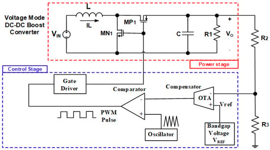
The integrated DC–DC converter is appropriate for use in many domains, namely, display, cellular, and portable applications. This paper presents an integrated control circuit for a monolithic voltage mode DC–DC boost converter for display driver applications. The control circuits consist of a transconductance amplifier, a comparator, and an oscillator. The boost converter consists of an inductor, two MOSFET, and an output RC filter. The control circuits are designed for fast transient response and low output ripple. The transconductance amplifier, comparator, and oscillator in the control circuit are designed to operate at a supply voltage of 3.3 V and an operating frequency of 5.5 MHz. The transconductance amplifier consists of an operational amplifier and an RC filter in the feedback path. The RC filter has a pole with a sufficient phase margin for high stability. The control circuits are realized in a 0.35-μm CMOS process together with the DC–DC converter. The fabricated DC–DC converter was evaluated by experiment and simulation. Testing of the proposed control circuits shows that the output transient time can be controlled within 7 μs, and the output voltage is accurately controlled with a ripple ratio of 3%.

Electronics, Free Full-Text, backrooms level negative 974
Electronics, Free Full-Text
Sensors, Free Full-Text
Electronics Magazine (1966-10-31) : Free Download, Borrow, and Streaming : Internet Archive

SOLUTION: Fundamentals of power electronics by r w erickson - Studypool
Electronic Experimenter's Handbook 1984 (1983) : Ziff-Davis Publishing : Free Download, Borrow, and Streaming : Internet Archive
Speech Scrambler/ Descambler - Ramsey Electronics

TDR Prism, BPB Dirty VHS, VPRE-72: Free Plugins of the Week

Accelerate Electronics